
Conceptual to Logical with Polyglot relationships
Data modeling is not about rigid layers or debating where conceptual ends and logical begins. In real projects, what matters is clarity, collaboration, and the ability to move forward with a shared understanding.
In Hackolade Studio, Polyglot models are designed with this pragmatic mindset. Rather than enforcing strict boundaries between conceptual, logical, and physical modeling, Polyglot provides a flexible modeling space that can serve different purposes, depending on your context and objectives.
Conceptual modeling is key to agree on scope and concepts, and to establish a shared language of business terms and definitions. By focusing on common terminology, it helps to prevent misunderstandings and it sets the foundation for clear communication, especially in large or cross-functional teams. Using Ubiquitous Language principles, this level aligns stakeholders before diving into technical details.
Logical modeling defines a neutral, unified data structure that transcends specific technologies, to capture the business rules necessary to ensure the integrity of the data. It serves as a blueprint for creating various physical models.
Physical modeling customizes the design for the technical specifics of each platform (e.g., relational databases, NoSQL, Graph databases, APIs, Big Data). This model ensures that the design works within the constraints of the chosen technology and optimizes implementation. Hackolade Studio supports more than 40 physical targets, allowing for tailored models that fit your specific platform.
Our Polyglot model provides a flexible way to move between these different phases, leaving it up to each organization to decide where emphasis should be placed.
Model relationships with purpose
Relationships in Polyglot follow the same philosophy. They are designed to help you express meaning and structure first, without being constrained too early by implementation details such as foreign key constraints, join tables, or platform-specific rules. We make it easy to discuss concepts with business users, who might not be familiar with the technical aspects of data modeling, so as to focus on facts.
When starting from a blank canvas, you may only know that certain concepts are connected. At this stage, the goal is not to decide how these relationships will be implemented in a relational database, a graph, or an API. The goal is to make relationships explicit, understandable, and shared across stakeholders.
As the model evolves, relationships can be progressively enriched with additional information such as direction, cardinality, or roles. Polyglot allows this gradual refinement, supporting both high-level conceptual discussions and more detailed logical designs within the same model.
In the following sections, we walk through a simple order management use case, starting from a very high-level conceptual view and progressively refining relationships. Each step illustrates both the underlying concepts and how they are represented in the Hackolade Studio user interface.
The objective is not to prescribe a single “correct” way to model relationships, but to show how Polyglot gives you the freedom to model at the right level, at the right time, with purpose.
To illustrate how relationships are created and refined in a Polyglot model, we will use a simple order management use case.
This example is intentionally simplified. It does not aim to represent a complete or realistic production system, but rather to focus on the modeling approach and the underlying reasoning. The objective is to demonstrate how relationships can be expressed progressively, starting from a high-level conceptual view.
Identify the core concepts
At the very beginning of the modeling process, a few key concepts have been identified:
- Customer
- Order
- Product
At this stage, no assumptions are made about attributes, cardinalities, implementation details, or target technologies.
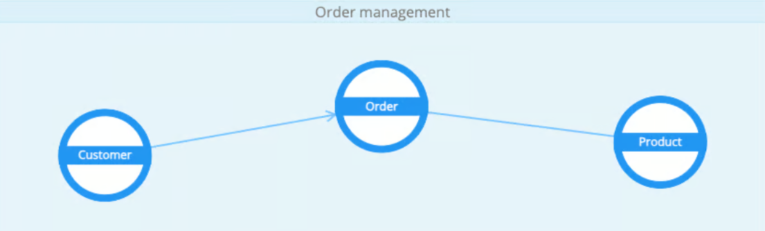
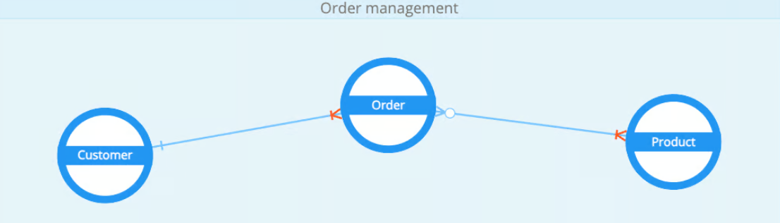
The model starts as a blank canvas with three entities representing the main business concepts involved in an order management system.
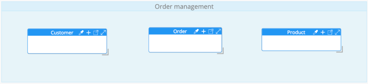
From this initial state, we will progressively define and refine the relationships between these entities, moving from a very conceptual representation toward a more structured and explicit model.<br>
Create your first relationship: Customer and Order
The first relationship we introduce reflects a simple and widely understood business fact:
A Customer places an Order.
Create the relationship from the Graph Diagram view
The most natural way to express this relationship between 2 entities is directly from the Graph Diagram view, which is well suited for early conceptual modeling. This view is accessible from the main modeling area using the tabs located at the bottom of the screen.

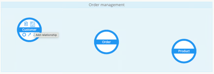
In this view, each entity is represented as a node. To create the relationship:
- move the mouse over the Customer node;
- on hover, click the link icon displayed in the top-right corner of the node;
- the cursor switches to relationship creation mode (plus icon);
- click the Order node to complete the relationship.
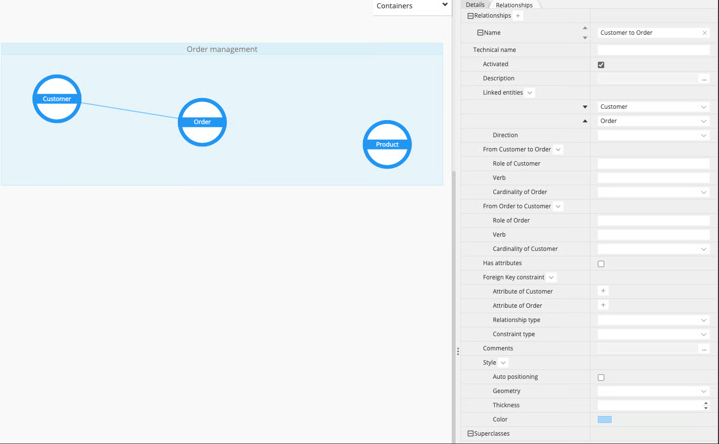
A relationship is immediately created between Customer and Order and becomes visible in the Graph Diagram View. Right after creation, the relationship is automatically focused and highlighted in the model’s Relationships tab, and its details are shown in the Properties pane.
At this stage, the relationship only expresses that the two entities are linked. No direction, cardinality, or structural constraint has been defined yet. The intent is purely semantic: making the existence of a relationship explicit, without going beyond what is known at this point.
Create a relationship from the Properties Pane
To illustrate the alternative creation method, we now create the relationship between Order and Product directly from the Properties Pane.
In the model’s Relationships tab, click the plus button to add a new relationship. A new relationship entry is created and automatically focused. At this point, the relationship is intentionally empty: no entities are linked yet. The source and target entities can be selected using the drop-down lists.
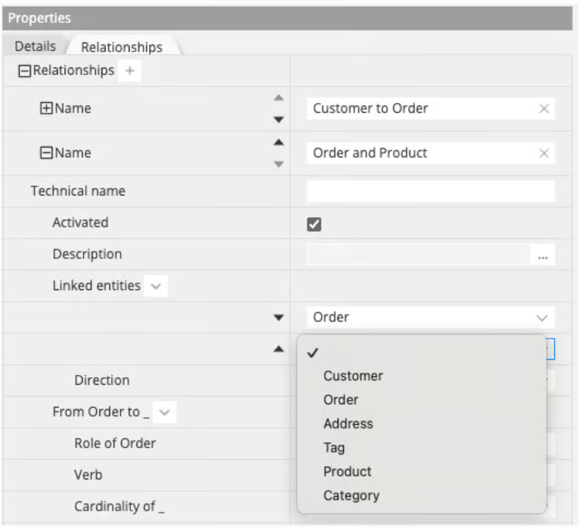
By selecting Order and Product, the relationship is defined and becomes part of the model.
Note that you can also create relationships from:
- the Diagram Objects Pane
- the Actions > Add Relationship menu
- the Add Relationship icon in the toolbar
- the Add Relationship option in the Contextual Menu
or via drag-and-drop of attributes from parent to child or child to parent, depending on your configuration.
Enrich the relationship: direction, roles, verbs, and cardinalities
At this point, 2 relationships have been created:
- Customer-Order using the diagram,
- Order-Product using the Properties pane.
The next step is to progressively enrich a relationship with additional information. We start with the direction, which defines how the relationship is read and understood.
Direction as a semantic choice
In Polyglot, direction is primarily semantic. It defines the direction in which the relationship is read, especially in combination with verbs and roles.
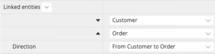
Using the Customer-Order relationship, the direction can be set explicitly (for example From Customer to Order), but it is not mandatory.
In the Linked entities section, arrows are available to swap the start and end entities, allowing you to reverse the reading direction when needed.
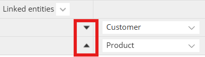
It is also possible to mark the relationships as bi-directional.
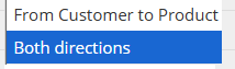
For example, a relationship "is paired with" (a phone and a Bluetooth device) would be bi-directional.
From a conceptual perspective, neither entity is inherently more important than the other. The choice of direction and its visual representation depends entirely on what makes sense for your modeling intent.
Once a direction is set, a visual arrow is displayed on the diagram. Depending on how the relationship is configured, this arrow can be shown in one direction, in both directions, or not shown at all.
At this stage, no notion of parent or child is imposed. At a conceptual level, entities can remain simply linked without enforcing a direction.
Reading the relationship in both directions
A relationship can be read in both directions: from one entity to the other, and vice versa. For each direction, Polyglot allows you to specify three pieces of information:
- a role,
- a verb,
- a cardinality.
Note that role and verb are for informational purposes only, and will not be propagated to the physical level.
These elements are intentionally grouped and ordered to support a clear and consistent reading of the relationship. To further simplify this reading, the property labels in the Properties pane dynamically adapt to the selected entities. When entities are swapped, the labels are automatically updated to follow the new direction, ensuring that roles, verbs, and cardinalities always remain easy to read and unambiguous.
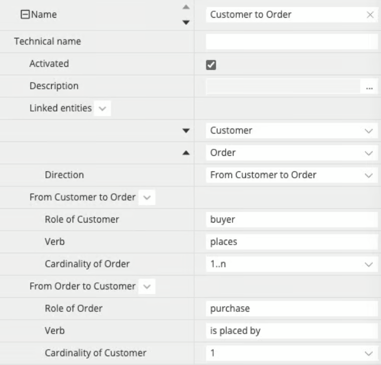
From Customer to Order:
- the role of the Customer is buyer (from the perspective of the Order),
- the verb is places,
- the cardinality of Customer is 1.
From Order to Customer:
- the role of the Order is shopping cart,
- the verb is is bought by,
- the cardinality of Order is 0..n.
The relationships can be read as:
- a Customer plays the role of buyer and places zero or more Orders.
- an Order is a shopping cart that is bought by exactly one Customer.
Framing roles and verbs from the reading perspective of the related entity helps clarify cardinalities. By structuring relationship metadata in this way, Hackolade Studio encourages a modeling flow that starts with facts, meaning and narration, and only then introduces structural precision. Once cardinalities are defined, they are reflected directly in the Graph Diagram view, where they replace simple directional arrows and enrich the visual representation of the relationship.
In both the Entity-Relation Diagram view and the Graph Diagram view, relationship information is depicted at each end of the relationship line:
- when cardinalities are defined, they are shown on the relationship ends, following Crow's foot notation;
- if no cardinality is specified, direction markers are depicted instead;
- if neither cardinality nor direction is defined, no marker is displayed.
At any time, you can switch back to the Entity-Relationship Diagram view, where the same information is presented using a more traditional ERD notation. In this view, each relationship provides a tooltip that summarizes the relationship semantics, including roles, verbs, and cardinalities, along with a readable sentence that validates the modeling intent.
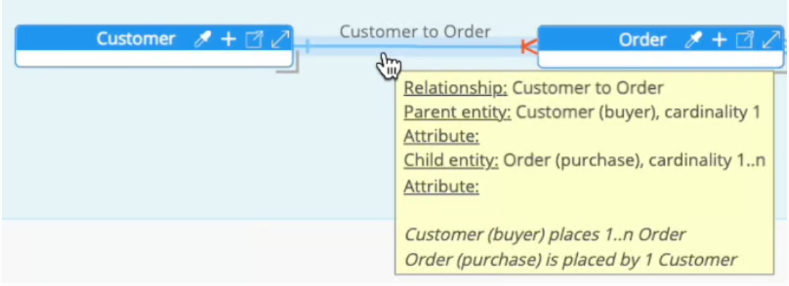
Both views are simply different visual representations of the same underlying Polyglot model.
From conceptual to logical: crossing the boundary
At this stage, the model has been enriched with additional semantics. Introducing roles and verbs usually still feels comfortably conceptual: they help tell a clear business story and make relationships readable and shared.
Cardinalities, however, are often the first element that makes some data modelers pause. For some, cardinalities already belong to logical modeling because they introduce constraints. For others, they remain part of a conceptual model, as they express business rules rather than implementation decisions.
There is no universal agreement on where the conceptual model ends and the logical model begins. In practice, this boundary is gradual and highly dependent on context, intent, and modeling culture. Debating strict definitions is often less valuable than ensuring the model makes sense for the people who use it.
Polyglot deliberately avoids enforcing a rigid separation. You may choose to continue evolving the same Polyglot model, accepting that the conceptual view is simply one step along your reasoning path. Alternatively, you can decide that this is the moment to preserve the model at its current level and derive a new Polyglot model to continue the refinement from a more logical perspective.
The choice is yours. What matters is not where you draw the theoretical line, but that the model remains clear, meaningful, and useful for your project and your team.
Reminder: with Diagram Views, you can create create different visualizations of the same diagram, each with its own Display Options to customize the view to your exact data model story-telling purpose. So it is possible to easily combine conceptual and logical views in the same Polyglot model.
Associative entity: add attributes to a relationship
Some relationships carry more information than the simple fact that two concepts are linked. This is typically the case for many-to-many relationships, where additional data belongs to the relationship itself rather than to either entity.
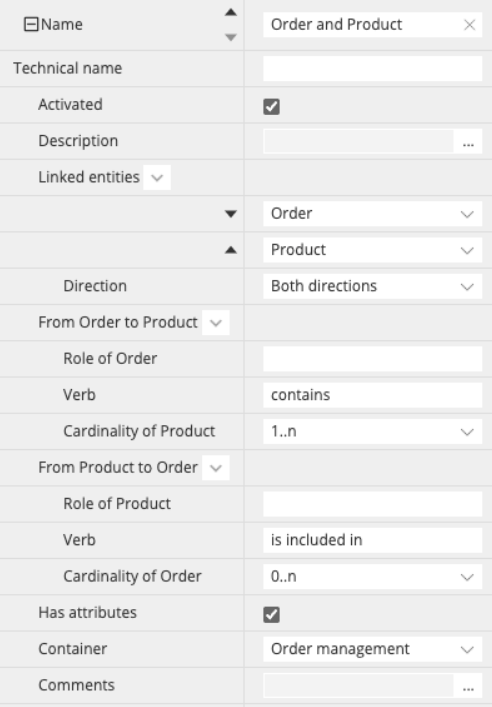
In our order management example, the relationship between Order and Product is a good illustration. An Order contains Products, but this alone is not sufficient. A crucial piece of information is missing: the quantity of each Product within an Order (and potentially other information such as price or discounts).
Enable attributes on a relationship in Properties Panes
In Polyglot, relationships can carry attributes when needed. This is controlled through the Has attributes property in the relationship’s Properties Pane. When this option is enabled, the relationship becomes capable of holding its own attributes, just like an entity.
For this step, it is recommended to switch to the Entity-Relationship Diagram (ERD) view, as this view makes relationship attributes immediately visible and easier to reason about.
Note: while in relational, a relationship with attributes is typically used in the context of a many-to-many cardinality and results in a junction table at the physical level, in Labeled Property Graph databases, it results in an edge relationship.
Once Has attributes is enabled, the relationship is represented as a dedicated association box between Order and Production. This box represents the relationship itself and provides a place to define attributes that belong to the association.
At this point, you can add an attribute named quantity to the relationship, using the same mechanism as when adding an attribute to an entity. This associative entity is visible in the ERD:

and also in the Graph Diagram:
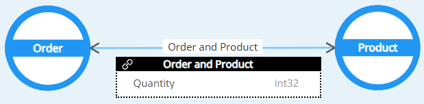
This makes the model explicit: the quantity is not a property of the Product, nor of the Order, but of the relationship between them.
Using relationship attributes allows you to model this information directly and clearly, without prematurely introducing additional entities. It keeps the model expressive while remaining aligned with the underlying business meaning.
Note: disabling the property Has attributes on a relationship that already contains attributes is a destructive action. All existing relationship attributes will be permanently removed. A warning dialog is displayed and you must explicitly confirm the action before the attributes are deleted.
When a relationship carries attributes, it represents an association between the two entities. This implies that the relationship will require an intermediate structure (such as a join table) to store those attributes in the materialization. For this reason, both entities involved in the relationship must belong to the same container or database, as the association needs to be managed within a single scope.
Add constraints and logical structure
Up to this point, the model has focused on meaning and structure: entities, relationships, directions, cardinalities, and, where needed, relationship attributes. The next step is to introduce constraints and move further into logical modeling.
This step is not about committing to a physical technology or deciding whether constraints will be technically enforced. The goal is to model reality more precisely and to make relationship rules explicit.
To define constraints, entities need to expose the attributes that participate in those relationships (for example, identifiers). How these attributes are defined is not the focus here; what matters is that they exist so relationships can be constrained accordingly.
Define relationship constraints
At this stage, you may choose to define foreign key constraints on relationships. This is optional and depends on your modeling intent. A foreign key constraint expresses that one entity holds a reference to another. In practice, this means identifying:
- a reference attribute (typically a primary key or a unique key, simple or composite) on one side,
- and a corresponding attribute on the other side that points to it.
Whether such a constraint will later be technically enforced, merely documented, or ignored depends on the physical targets derived from the model. That decision is outside the scope of this step. Here, the objective is simply to make the relationship explicit at the logical level.
In the order management example, this can be illustrated with the Customer-Order relationship:
- Customer exposes Customer ID as its primary key,
- Order carries Customer ID as a foreign key attribute,
- this attribute mapping expresses that each Order refers to exactly one Customer.
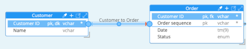
This constraint makes the dependency between Order and Customer explicit at the logical level, regardless of how (or whether) it will be enforced in a physical target.
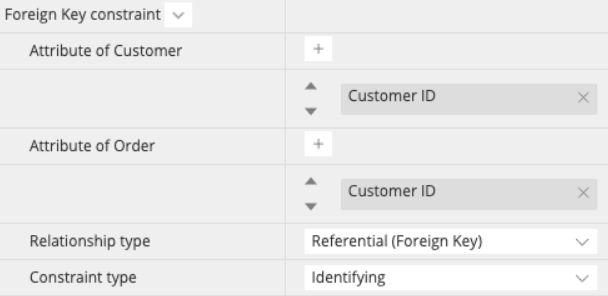
Additional constraint properties are available: the relationship type and the constraint type. These properties allow you to further qualify how the relationship should be interpreted at the logical level.
Relationship type
By default, a relationship defined through attribute mapping is interpreted as a referential foreign key (FK) relationship. This expresses that one entity holds a reference to another through a key-based pointer.
An alternative option is the foreign master (FM) relationship type. This option is useful in denormalized models, where attributes stored in an entity are not mastered there but are replicated from another entity. In this case, often seen in NoSQL databases, the relationship does not primarily express a key-based dependency, but rather indicates the origin of the replicated information.
Using a foreign master relationship makes it explicit that certain attributes are inherited from, or governed by, another entity, even if no strict foreign key constraint is intended.
Entity-Relationship Diagram (ERD) visual indicators
In the Entity-Relationship Diagram, selecting a relationship does not only show its relationship type. It also highlights the attributes involved on each side of the relationship so you can immediately see which attributes participate in the link.
To make this easier to read, the ERD displays also short markers next to the involved attributes:
-
For a referential foreign key relationship:
- fk is shown in the child entity next to the attribute that carries the foreign key (the pointer side).
- dk is shown in the parent entity next to the referenced key attribute (the destination key being pointed to).
-
For a foreign master relationship:
- fm is shown in the child entity next to denormalized (replicated) attributes.
- dm is shown in the parent entity next to the master source of those attributes (destination/denormalized master).
Note: the relationship line for a foreign master relationship is displayed with a dotted line, and requires that the Display Option is enabled for this type of relationship (which is disabled by default.)
Constraint type: identifying versus non-identifying relationships
In addition to the relationship type, you can specify whether the constraint is identifying or non-identifying.
This distinction is purely informative and reflects a modeling decision about identity:
- In a non-identifying relationship, the foreign key attribute does not participate in the primary key of the dependent (child) entity.
- In an identifying relationship, the foreign key attribute is part of the primary key of the dependent (child) entity.
It is important to note that there is no automatic coupling between this setting and the definition of primary keys. Marking a relationship as identifying or non-identifying does not automatically modify keys. It is the modeler’s responsibility to define primary keys and foreign keys in a consistent and coherent way.
The identifying versus non-identifying distinction is therefore a semantic aid, not an automated rule. Its purpose is to help document intent and support clear reasoning about identity within the model. This information is available in the tooltip on Entity-Relationship Diagram view.
When you create a foreign key relationship using drag-and-drop
In addition to creating relationships progressively, it is also possible to create a relationship directly at the attribute level in the ER Diagram view.
When entities and attributes already exist, you can create a relationship by dragging-and-dropping an attribute onto another attribute, in the same entity for recursive relationships, or in a different entity. This action immediately creates a foreign key relationship, including the attribute mapping, without going through the conceptual steps.
This approach is particularly useful when working in a more logical or schema-driven workflow, where identifiers and attributes are defined first and the goal is to quickly express referential constraints.
When creating a relationship using drag-and-drop between attributes, the default direction (from parent to child or from child to parent) is determined by your configuration. This behavior can be adjusted in Tools > Options, where you can define how relationship direction is inferred during attribute-level creation.
In addition to the creation direction, you can also configure the default relationship name. This setting allows you to control how relationship names are automatically generated, based on the linked entities and/or the attributes involved.